If you’ve ever popped the hood of a modern car, zipped down a highway with adaptive cruise control, or cooled the cabin with a whisper-quport electric blower, you’ve used an automotive brushless motor. These motors aren’t just a step up from their brushed predecessors—they’re the backbone of today’s electric and electrified vehicle systems, from powertrain to auxiliary parts. As a supplier who’s worked with automakers and part integrators for over a decade, I get asked the same question over and over: How do we control their speed so precisely, especially under the messy, high-stress conditions of a car or truck? The answer isn’t just a simple switch or dial. It’s a carefully tuned system of electronics, software, and engineering built to balance performance, efficiency, and longevity. Let’s break down the methods we rely on day in and day out to keep our brushless motors running right when our customers need them most. Automotive Brushless Motor

First, it helps to remember what makes brushless motors different from the brushed ones many of us grew up with. Brushed motors use physical brushes and a commutator to reverse current flow in the rotor, which creates speed and torque. That system generates friction, wears out parts over time, and limits how precise you can be with speed adjustments. Brushless motors, on the other hand, don’t have brushes. Instead, the permanent magnets sit on the rotor, and the stator (the stationary part of the motor) has copper windings that we energize in a sequence. To control speed, you have to adjust how and when those windings get power—no small feat, because you have to sync power to the rotor’s exact position, 10,000 times a minute in many cases.
The most fundamental control method we use in automotive applications is called Field-Oriented Control (FOC). Early on, when we first started scaling brushless motors for mass-market cars, most of us used something called trapezoidal control, which was simpler and cheaper. Trapezoidal control works by dividing the rotor’s 360-degree rotation into six equal segments. Each segment gets power in a fixed sequence, turning the windings on and off in pairs. It’s easy to implement, and it works well for basic systems like power windows or wipers, where speed doesn’t need to be super smooth. But here’s the thing: trapezoidal control isn’t very efficient at low speeds, and it can cause the motor to make a noticeable humming or even vibrate when running at constant speeds. That’s a big problem for modern vehicles, where quiet operation and energy efficiency are non-negotiable.
When automakers started pushing for better fuel economy and smoother performance, we shifted almost entirely to FOC, and for good reason. FOC treats the stator’s magnetic field not as six separate steps, but as a single, rotating vector that can be adjusted in real time to match the rotor’s position. Think of it like steering a boat: instead of making big, jerky turns, you make tiny, continuous adjustments to go exactly where you need to. The key to FOC is real-time feedback from sensors that track the rotor’s position. The most common sensors here are Hall effect sensors, which are small, cheap components that detect the magnetic field of the rotor and send a signal to the motor controller. For even higher precision—like in an electric vehicle’s traction motor—we use resolvers, which are a bit more complex but can track position with almost no error, even at high temperatures.
Wait, but what if we don’t want to add extra sensors to the motor? Adding components drives up cost and complexity, which is a no-go for automotive suppliers working on high-volume parts. That’s where sensorless FOC comes in, a method we’ve refined a lot over the last five years. Sensorless control uses the back-EMF (electromotive force) generated by the stator windings themselves to estimate the rotor’s position, instead of a separate sensor. When a brushless motor is running, the rotating magnetic field induces a voltage in the stator windings. That voltage changes depending on where the rotor is, so we can measure it and use algorithms to calculate speed and position. Early sensorless systems had a hard time working at very low speeds or when the motor was just starting up, because back-EMF is almost nonexistent there. But with better signal processing software and more powerful microcontrollers, we can now get reliable data from 0 RPM all the way to the motor’s maximum rated speed, which is critical for things like the electric power steering motor that has to respond the moment you turn the wheel.
Once we have the control method mapped to the rotor’s position, we still have to adjust the actual power delivered to the motor to change speed. That’s where Pulse Width Modulation (PWM) comes in, a method used in almost all automotive motor control systems. PWM works by switching the voltage to the stator windings on and off very quickly—thousands of times per second. The average voltage over time is what determines how much power the motor gets. For example, if you want half the power, you turn the voltage on 50% of the time and off 50% of the time. The frequency is so fast—usually between 10 kHz and 20 kHz—that no one can hear it, which is perfect for cabin-mounted motors like blowers or sunroofs. The key with PWM in automotive applications is making sure that switching doesn’t generate too much electrical noise, which can interfere with other systems like the infotainment or engine control unit. We use shielded wiring and filter circuits to minimize that noise, and it’s something we test rigorously at our in-house labs to meet strict automotive EMC (Electromagnetic Compatibility) standards.
But speed control isn’t just about adjusting power to the motor. We also have to account for external factors that change how the motor performs, right? A motor running a car’s cooling fan has to spin faster in the summer when the engine is hot than it does in the winter when the engine is cool. A power steering motor has to produce more torque when you’re parked than when you’re driving straight down the highway. That’s where closed-loop control comes in, a method that compares what we want the motor to do (its target speed) with what it’s actually doing (measured by the rotor position sensors or back-EMF) and adjusts power on the fly.
A typical closed-loop system for an automotive brushless motor works like this: The vehicle’s central control unit (ECU) sends a speed command to the motor controller—for example, “spin the blower at 3,000 RPM.” The controller reads the actual speed from the sensor, calculates the difference between the target and actual speed (called the error), and adjusts the PWM or FOC parameters to fix that error. The controller runs this loop hundreds of times per second, so if the fan hits a sudden gust of wind from driving on the highway and slows down even a little, it will instantly add a little more power to get back to 3,000 RPM. This is how we get that smooth, consistent performance that drivers don’t even notice—until it works, that is.
There are also specialized speed control methods for specific automotive systems, which is something we spend a lot of time customizing for different customers. For example, in electric vehicles (EVs) and hybrid electric vehicles (HEVs), the traction motor doesn’t just control speed—it controls torque, and it has to work over a huge range of speeds, from 0 RPM (when the car starts moving) up to 15,000 RPM or more. For these systems, we combine FOC with field weakening, a method that adjusts the stator’s magnetic field to allow the motor to spin faster than its natural limit. At high speeds, the rotor’s permanent magnets generate their own magnetic field that can fight against the stator’s field, limiting speed. Field weakening uses a small current to slightly offset that rotor field, letting the motor reach higher speeds without sacrificing efficiency. That’s a huge part of making EVs work at highway speeds, and it’s a technology we’ve invested heavily in over the last decade as EV production has exploded.
Another specialized area is for auxiliary motors, which are the smaller motors that do everything from operating the liftgate to adjusting the side mirrors. These motors don’t need to spin as fast as traction motors, but they do need to be reliable over hundreds of thousands of cycles, often in harsh environments with extreme temperatures, moisture, and vibration. For these, we often use a simpler version of trapezoidal control paired with PWM, because it’s cost-effective and less complex to integrate. We also add overcurrent protection circuits to make sure the motor doesn’t burn out if it gets stuck—like if someone puts their hand in a closing power window. That’s a non-negotiable safety feature in automotive applications, so we build that into every control system we design, no matter how simple the motor is.
I’ve seen a lot of changes in this space over my time as a brushless motor supplier. Ten years ago, most auxiliary motors were brushed, and speed control was just a single relay that switched between high and low. Now, 90% of automotive motors are brushless, and speed control has become so precise that we can adjust the speed of a cabin blower by 1 RPM increments, so you never have a draft or a lull in airflow. We’ve also had to adapt to new requirements, like stricter emissions standards that need cooling fans to run more efficiently, and advanced driver-assistance systems (ADAS) that need power steering motors to respond in milliseconds.
One common misconception I hear from people outside the industry is that speed control is just “turning a dial.” But anyone who’s worked with automotive systems knows that’s not the case. A motor that works fine in a lab at 25 degrees Celsius (77 degrees Fahrenheit) will perform totally differently at -40 degrees Celsius (-40 degrees Fahrenheit) in northern Canada or 120 degrees Celsius (248 degrees Fahrenheit) under the hood of a truck in Arizona. We test every control method in extreme temperatures, vibrational environments, and even at high altitude to make sure it works when the customer needs it, not just in ideal conditions. We also use redundant circuits in critical systems, like traction motors, to make sure if one sensor fails, the controller can still adjust speed reliably, which is required by automotive safety standards like ISO 26262.
If you’re working in automotive engineering, whether you’re designing EVs, upgrading auxiliary systems, or troubleshooting a tricky motor issue, the key takeaway is that there’s no one “right” speed control method. The best approach depends on the application: do you need high precision for a traction motor, or low cost for a power seat? Do you have space for a resolver, or do you need sensorless control to save room? We work with every type of automotive OEM and tier 1 supplier to design custom speed control solutions that fit their specific needs, balancing performance, cost, and reliability.
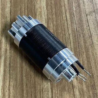
At the end of the day, the goal of speed control for automotive brushless motors is simple: deliver consistent, efficient, and reliable performance, no matter what the vehicle or environment throws at it. We’ve come a long way from the early trapezoidal systems of the 2000s, and as EV adoption grows, we’re continuing to refine FOC, sensorless control, and field weakening to meet even higher demands. If you’re looking for a partner to develop or source automotive brushless motors with precise, robust speed control for your next project, we’d be happy to discuss your requirements, share our design capabilities, and work with you to find the right solution. We collaborate with clients of all sizes, from small startup EV companies to large global automakers, and we pride ourselves on delivering solutions that meet strict automotive standards and stand up to real-world use.
Medical Brushless Motor References
- Bose, B.K. (2013). Modern Power Electronics and AC Drives. Prentice Hall.
- Miller, T.J.E. (2008). Electronic Control of Switched Reluctance Machines. Elsevier.
- International Organization for Standardization (2018). ISO 26262: Road Vehicles – Functional Safety. ISO.
- CHRYSLER GROUP LLC. (2016). Automotive Electrification Systems: Motor Control Fundamentals. SAE International.
- De Doncker, R.W., Divan, D.M., & Kioskeridis, P. (1996). “The Drives for the Next Century.” IEEE Transactions on Industry Applications, vol. 32, no. 2, pp. 265-273.
Shenzhen HengDrive Technologies Co., Ltd.
Shenzhen HengDrive Technologies Co., Ltd. is one of the most professional automotive brushless motor manufacturers and suppliers in China, specialized in providing high quality customized service. We warmly welcome you to buy the newest automotive brushless motor in stock here from our factory.
Address: Building A & F, FuNing Hi-Tech Park, XinTian Road, FuHai Street, BaoAn District, ShenZhen, GuangDong Province, China.
E-mail: Marketing001@hengdrive.com
WebSite: https://www.hengdrivemotor.com/
