If you’re sourcing precision shafts for industrial machinery, automotive components, or even medical devices, you know that concentricity is non-negotiable. A shaft with even minor concentricity deviation can throw an entire assembly off—causing premature wear, vibration, excessive noise, or even catastrophic failure down the line. As a shaft supplier with over 18 years in the business, I’ve worked with hundreds of engineers to get this right, and today I’m pulling back the curtain on the actual, actionable methods we use to ensure concentricity for every shaft we ship. No generic industry jargon, no flashy tech that only works in a lab—just real-world strategies that have stood the test of thousands of client orders. Shaft
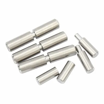
First, let’s ground this: concentricity, in basic terms, is how closely the central axis of a shaft’s outer diameter matches the central axis of its bore, keyways, or any other feature. For a shaft driving a hydraulic pump, for example, if the outer rotating surface and the inner bore where it mounts are off by even 0.001 inches, the pump will leak and burn out in months. So let’s walk through the entire process—from raw material to final inspection—because concentricity isn’t fixed in one step; it’s built into every stage of production.
Starting with raw material selection and preparation, this is the foundation. I’ve seen suppliers cut corners here by using low-grade bar stock without verifying its initial roundness, which dooms concentricity before machining even begins. For high-precision applications, we always start with cold-drawn steel or alloy bar stock that’s already precision-ground to within ±0.0005 inches in roundness along its entire length. Hot-rolled bar stock, while cheaper, often has inherent ovality from the mill that requires extra machining to fix, and that variability makes consistent concentricity hard to hit. Before we even load a bar into a CNC machine, we run a quick on-material check: we mount the raw stock between centers and use a dial indicator to scan the outer diameter. If it deviates more than 0.0005 inches at any point, we reject it immediately. I once had a client send us a batch of 50 shafts where the previous supplier used uninspected hot-rolled stock; every single one had concentricity deviations over 0.002 inches, and we had to re-machine each from scratch to meet their specs. That’s the kind of mistake we avoid by not skipping this raw material step.
Next, workholding is the unsung hero of concentricity. No matter how accurate your CNC machine is, if you don’t hold the shaft securely and aligned during machining, you’ll never get a consistent axis. Let’s be clear: generic 3-jaw chucks are a no-go for precision concentricity. Their self-centering design works for rough cuts, but the offset from the chuck jaw tolerances adds up—especially when machining features that need to align along the shaft’s entire length. For precision work, we use either dead centers and a lathe dog, or 4-jaw independent chucks with trueing, or even collet chucks for smaller, high-volume shafts. Wait, you might be thinking: collet chucks are for small parts, but no—we use hardened steel collets that are precision-ground to within ±0.0002 inches for shafts up to 6 inches in diameter, and they hold the part’s entire outer surface evenly, eliminating the jaw offset. For larger shafts (8 inches and up), we use a combination of live centers at both ends: the tailstock center has a slight floating design that compensates for minor variations in the bar stock length, and the headstock center is precision-ground to match. A mistake I see new machinists make is overtightening the tailstock center, which bends the shaft and creates artificial concentricity deviation. We train our team to tighten the tailstock just enough to eliminate play, not so much that it deforms the part. I once had a client who kept getting inconsistent concentricity on 10-inch shafts until we showed them their previous supplier was overtightening the tailstock—each shaft was bent during machining, so when they measured it after removing it from the machine, the axis shifted. That’s workholding 101, but it’s often overlooked.
Then comes the machining process, split into roughing and finishing, which is where most concentricity errors creep in. Here’s a key rule we follow: for features that require concentricity to the shaft’s main axis, we machine all of them in a single setup whenever possible. What does that mean? If we’re machining a shaft that has a central bore, two bearing journals, and a keyway, we don’t unclamp the shaft and reposition it between operations. Unclamping it moves it off the axis, and even a tiny repositioning offset (0.001 inches or less) will throw concentricity off. Instead, we load the shaft once in the workholding, then machine the outer journals, bore, and keyways all in one go. For longer shafts that can’t fit in a single machine setup (like 4-foot-long shafts for large industrial gearboxes), we use CNC turning centers with sub-spindles. The main spindle machines one end, then the sub-spindle grips the opposite end of the shaft without unclamping it from the first operation, so the axis stays consistent. That sub-spindle grip is precision-ground to match the main spindle’s centerline, so there’s zero offset between operations. Roughing cuts also matter: we leave a consistent 0.010-inch stock for finishing, no more, no less. If we leave too much, the finishing cut will have to remove more material unevenly, causing the shaft to flex and shift during the cut, which throws concentricity. We also use sharp, rigid tooling—cheap inserts that are dull or have run-out will create uneven cutting forces, bending the shaft mid-cut. I’ve seen a $0.50 insert add 0.003 inches of concentricity deviation on a 12-inch shaft; that’s how small these variables are.
Now, heat treatment. This is a step that makes or breaks concentricity for shafts that need strength—like automotive crankshafts or heavy-duty transmission shafts. Heat treatment (case hardening, induction hardening, or through-hardening) introduces distortion, and that distortion is the number one cause of hidden concentricity errors after machining. A common mistake is machining the shaft, heat treating it, and then calling it done—but heat treatment can cause the shaft to bow, twist, or shift its axis by 0.005 inches or more, enough to ruin concentricity. That’s why we use stress relieving and precision grinding after heat treatment. After hardening, we run a low-temperature stress relief cycle (300-400 degrees Celsius) to reduce internal material stresses that cause distortion, then we precision-grind all critical features in a single setup, exactly referencing the original axis. Wait, grinding is different from turning, right? Grinding removes tiny amounts of material (0.001-0.005 inches per pass) with an abrasive wheel, so it can correct for the minor distortion from heat treatment. We use CNC cylindrical grinders with computer-controlled axis alignment, and the wheel is balanced before every run—even a slightly unbalanced wheel can create a spiral cut that adds concentricity error. For high-volume shafts, we even use in-process grinding measurement: sensors on the grinder scan the shaft’s outer diameter and bore in real time, adjusting the wheel position to keep the axis consistent. I once had a client who ordered shafts for electric motor rotors; they came to us after heat treatment with 0.004 inches of distortion, and standard turning couldn’t correct it. Our grinder with in-process measurement fixed it to their required 0.001 inches concentricity, and their motor’s vibration dropped by 70 percent. That’s the payoff of handling heat treatment properly.
Finally, inspection and validation—you can’t trust concentricity numbers just from the machine’s readout; you need hands-on, calibrated measurement that matches the client’s use case. Here’s what we do at our facility: first, we use a coordinate measuring machine (CMM) for high-precision shafts, but for fast, in-process checks, we use a precision dial indicator mounted on a granite base with V-blocks. Wait, V-blocks are critical here—when measuring concentricity, you need to support the shaft evenly along its length, and V-blocks prevent it from rocking or shifting. We use hardened steel V-blocks calibrated to within ±0.0001 inches, so they don’t wear over time. When measuring concentricity, we mount the shaft in two V-blocks that align with the shaft’s centerline, then move the dial indicator along the outer diameter and any internal features (like a bore). The total runout we measure is twice the concentricity deviation, so we halve that number to get the true value. But here’s a trick: we measure at multiple points along the shaft, not just one. A shaft might have perfect concentricity at its midpoint but be off at the ends if it’s bowed, so we scan every 2 inches along the length. For critical applications, we also perform functional testing: we mount the shaft in a test bearing assembly, spin it at its operating speed, and measure vibration with a proximity sensor. That’s different from lab measurements because it mimics how the shaft will actually be used. I had a aerospace client that initially approved a batch of shafts based on CMM numbers, but when we did functional testing, we found a tiny 0.0008-inch deviation at the end that caused vibration in their satellite’s reaction wheel. We re-ground those shafts and caught it before they were shipped—something that would have cost them millions if it had happened in space.
Now, let’s talk about common mistakes that even experienced suppliers make, because that’s where most of our clients’ problems come from. The first is not documenting concentricity at every step. We keep a build sheet for every shaft that records raw material roundness, workholding used, machining setups, heat treatment distortion, and final measurement data. If a shaft is rejected, we can trace exactly where the error happened—whether it was a bad insert, overtight tailstock, or distorted heat treatment. The second is using a single tolerance for all applications. A shaft for a paper mill might need concentricity within 0.005 inches, while a shaft for a medical insulin pump needs 0.0001 inches, and we adjust every step accordingly—no one-size-fits-all. The third is skipping pre-production testing. For new client orders, we machine and test one prototype first, validate its concentricity, then adjust our process for the full run, so we don’t waste material on bad parts.
At the end of the day, concentricity isn’t about using the fanciest CNC machine or the most expensive tooling. It’s about controlling every variable—from the bar stock you start with to the final vibration test—so that the shaft’s axis stays consistent, every step of the way. We’ve supplied over 2 million shafts to clients across automotive, aerospace, agriculture, and industrial automation, and the number one feedback we get is that our shafts eliminate the vibration and failure they were seeing with previous suppliers. That’s because we don’t just “make shafts”—we build precision components where every feature lines up exactly as specified.
If you’re working on a project that requires precise, consistent shaft concentricity, and you’re tired of parts that fail prematurely or don’t meet your specs, we can help. Whether you need a custom prototype, a high-volume production run, or a replacement for underperforming shafts from another supplier, our team can walk through your requirements, adjust our process to meet your tolerance, and deliver parts you can trust. Reach out to discuss your needs, and we’ll provide a detailed build plan and sample inspection data for your review.
Connector References:
- Todd, R. H., Allen, D. K., & Alting, L. (1994). Manufacturing Processes for Engineering Materials. Prentice Hall.
- Kalpakjian, S., & Schmid, S. R. (2020). Manufacturing Engineering and Technology (7th ed.). Pearson.
- Groover, M. P. (2019). Fundamentals of Modern Manufacturing: Materials, Processes, and Systems (7th ed.). Wiley.
- American Society of Mechanical Engineers (ASME). (2019). Dimensioning and Tolerancing (ASME Y14.5-2018). ASME International.
Kunshan Haizhijie Precision Hardware Co., Ltd.
As one of the most professional shaft manufacturers and suppliers in China, we’re featured by quality products and good price. Please rest assured to buy customized shaft made in China here from our factory. Also, pricelist is available.
Address: No. 367, Kangzhuang Road, Zhou City Town, Kunshan City, Jiangsu Province, China
E-mail: wzhshui@sina.com
WebSite: https://www.hzhjmetal.com/
